You are here
Logic Simulation
Logic simulation is an essential part of digital circuit design. Logic simulation and verification are used to verify the functionality described by a design description against output values expected at the output ports of a digital integrated circuit.
There are mainly three classes of logic simulators:
- compiled code logic simulators,
- event-driven logic simulators,
- compiled-code event driven simulators.
Compiled code logic simulator
Compiled code logic simulation algorithm evaluates every logic element in the design at each time step. Earliest logic simulators were compiled code simulators. In a compiled code simulator a combinational circuit is topologically ordered and equation is generated for each gate output in terms of its inputs using boolean operators AND, OR and NOT. Compiled code simulator evaluates every circuit element for every new input pattern. Two limitations of compiled code simulators are:
1. Their inability to handle asynchronous feedback.
2. lack of accurate timing and delay information in their models.
Also since circuit activity is very low at each element, run time of such algorithm is huge for big circuits. A large part of design cycle is taken up by circuit simulation.
Interpretive Event Driven logic simulator
Event-driven logic simulator works on the principle that output of a logic element changes only when one of its inputs change. An event-driven logic simulator evaluates a logic element when an event occurs on one of its inputs. Statistical data shows that event activities in large circuits are very low and with increase in size of the circuit percentage activity on a logic element decreases.
Each Concurrent process is converted to an Abstract syntax tree. When a process is executed its tree is traversed, nodes of the tree are interpreted and acted upon till the process suspends. A process may suspend when it finishes or due to non-availability of one of inputs. A suspended process is scheduled by scheduler to wait for some event to wake it up. Execution of some statements in a process may resume other processes.
There are two major classes of event driven logic simulation algorithms:
1. Synchronous simulation algorithms : These algorithms are centralized-timed and are used for single processor machine. The algorithm follows the path of events in the circuit. Simultaneous events are handled through centralized control of time. In this scheme simulation does not advance until all the events that occurred on current simulation time are processed. To implement this algorithm one needs to store events in global ordered queue of events which is circular in nature. Each slot in this queue represents simulation time and it stores a linked list of events that occur at that simulation time.
As the events of current time slot are processed, output of those events is compared the previous output of corresponding logic elements and if they differ new events are generated on logic elements whose input is driven by output of current event.
Synchronous event-driven simulation algorithm:
While (simulation-time < simulation-end-time) and (not termination-condition) {
For each time slot in the timing wheel{
For each partition in the current time slot
Update phase
If (output value from partition != corresponding logic element’s output)
Update inputs of all fan-out gates and set their evaluation marks.For each partition in the current time slot
Schedule phase{If (output value from partition != corresponding logic element’s output){
logic element’s output = output value from partition
Evaluate the fan-out elements whose evaluation marks are set and insert their computed outputs in future queue slots according to their delays. Clear their evaluation mark.}
}
Increment simulation-time and move to next time slot.
}
}
2. Asynchronous Simulation Algorithms: In asynchronous simulation there is no global centralized time. Instead each data item carries a time stamp which is indicative of time up to which data is valid. The evaluation of an event depends on availability of a token. Asynchronous algorithm can process events that occur at different time instances. Hence it can extract more parallelism compared to synchronous simulation algorithms.
The key component of asynchronous algorithms is how to decide the time stamp of a data element. There are different conservative and optimistic approaches.
2.1 In conservative schemes only safe evaluation time is allowed, evaluations which guarantee correct result. A logic element is evaluated only after it receives all its input tokens. As a logic element is evaluated its output is decided on the basis of its inputs and time stamp of output is decided by time stamp of last arriving token and delay of the logic element.

2.2 In optimistic scheme evaluation of a logic element takes place as soon as an input token arrives at its input. If the output produced turns out to be incorrect then roll back takes place to return to previous know correct state and messages are sent to forward elements to cancel effect of incorrect message sent earlier. This algorithm does not lead to deadlocks but has an added cost of state saving and more complex control mechanism because of rollback. Optimistic scheme is most efficient as long as rollbacks are few.

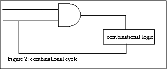
One disadvantage of Conservative scheme is that it can lead to deadlock. If an input of a logic element is driven by one of its output or output of a forward logic element then it leads to deadlock.
There exist both deadlock detection and deadlock prevention schemes to take care of this situation.
Compiled-code Event driven simulation
Modern simulators employ the good of both the worlds. Compiled code event driven simulator compiles the HDL description of the design to machine code. Generated code is then linked with simulator kernel. Kernel of the simulator handles scheduling and fanout processing.
